I get some questions about my transaxle and since I am not planning milling the billet 6082 aluminium intermediate flange I thought I'll help you guys out.
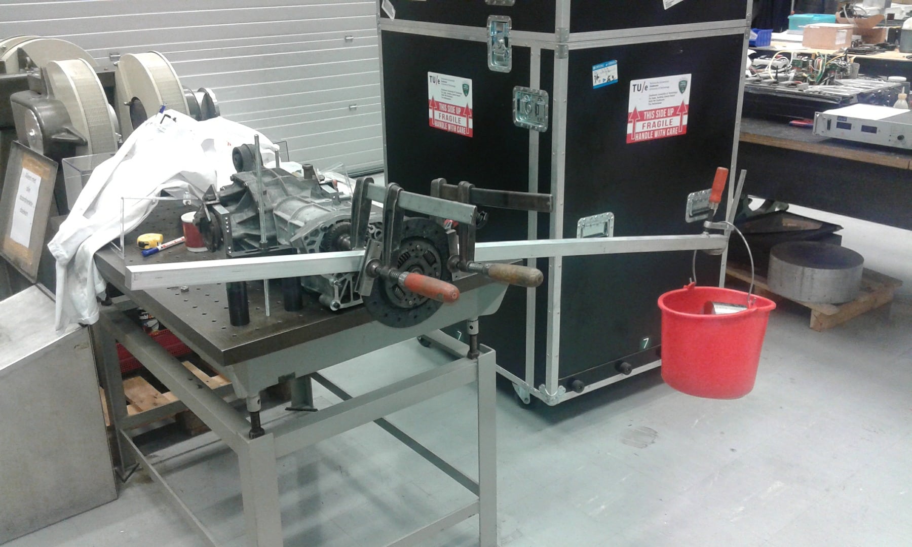
Here's how i built my transaxle on the supercharged 75. I did some trackday with it and one or 2 drift days.
Never had a failure on the transaxle. Also the car has done about 15000km's of hard road driving with lots of full accelerations in all gears.
First of all i want to point out your starting point is a gearbox with nice internals.
Check the bronze bushing in the gears and that the tollerance have to be factory spec.
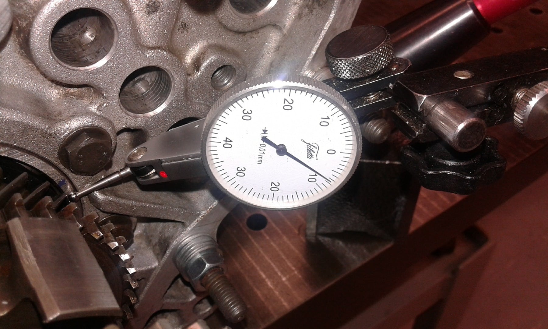
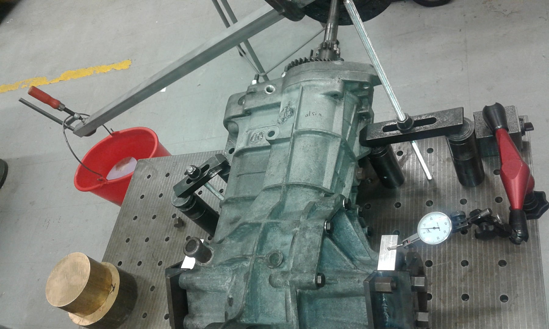
Check the backlash of the crown and pignon gears.
Check all ballbearings for wear.
Modification list of the box:
Upgraded clutch.
front gearbox mounts.
Needle bearing upfront in pignon shaft.
upgraded bearing plate
gearbox brace
gearbox cooling
Neelde bearing upfront:
The main and secondary shaft see a lot of flex when loading the box so i installed a needlebearing on the main shaft to battle the flex.
The old bush upfront had major wear to one side which shows the flex of the shaft. It was about 0.5mm oval to one side.

Needle skf hk 2520 . Mill out hole in gearbox housing to 32mm N7 press fit to get correct install.
If main shaft is damaged where the needle bearing is you have do lathe it to a smaller diametre and instal a hardened bush which is what i did.
Upgraded bearingplate:
This plate is added to maintain pignon backlash under hard acceleration.

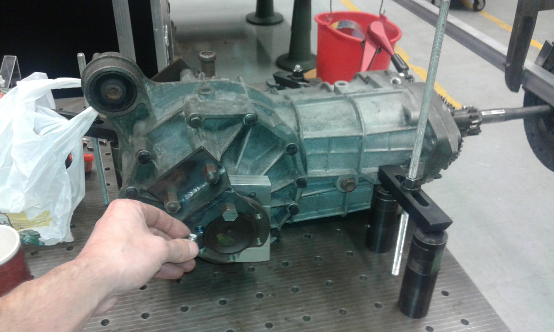
Gearbox brace:
Made for extra clamping force. Barry from south africa had problems with race alfa's HP levels above, i thought 350HP, pushing box halves apart so i built the brace just to be sure.


The studs between the upgraded bearingplate and the diff have right and left handed threads in them so you can put a mild tension on the brace after intalling it on the box. The left side has an extra aluminium milled block to attach the brace.
Gearbox cooling:
To maintain propper backlash oil cooling is needed. The shaft are of steel and the housing is of alluminium. So when gearbox temps go op backlash increases. I thought it is about 0.2mm at a delta T of 80 degrees and that's way out of spec.
Parts needed:
oil pump
oil filter
thermostat
some hoses/ clamps
Oil cooler

Oil is being succed out at the drainige plug then going to the filter, then the pump, oil cooler and inserted upfront where i drilled an extra hole. The extra hole is not in this picture. It is a mod i did later on for better circulation across al gears. In the brace i drilled an extra hole for a thermostat probe.
Geabox mounts:
Just built them because original last not that long with the torque levels. Also verry nice when you do clutch work beacuase you can sepparte them when pulling out central bush bolt.

Hope i did not forget something. It is a while when i did this. Hope it helps out someone.
Sent me a PM for stepfiles of the bearingplate and extra brace diff mount plate. The forum won't let me upload the files unfortunately.