Page 1 of 1
Crank pulley dynamic balance
Posted: Wed Oct 06, 2010 3:02 am
by scott.venables
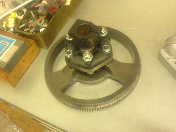
G'day guys. I thought it would be an interesting project to see how much weight I could machine off the crank pulley for my 2.5. It was going well until I started thinking about the axial movement of the counter weight. Pictured below is the jig I made for static balance. The pair were balanced together before I started machining.
I've machined the front back to the middle of the front V groove (originally a 3 groove pulley) which is pretty close to 25mm and to maintain the static balance the non counter-weighted areas on the back and in the ID have been machined away.
The static balance can easily be restored but the question is, how worried should I be about the axial position of the counterweight?
Any ideas would be much appreciated
Cheers, Scott
Re: Crank pulley dynamic balance
Posted: Wed Oct 06, 2010 10:56 am
by gran turismo
Moving the counterweight forward on the crank will increase the dynamic bending stress on the crank. This will affect the dynamic balance of your motor. How much? I don't know.
Also, I have heard of catastrophic failures of cast iron flywheels lightened with radial holes similar to your cast iron pulley. This may not be an issue since the diameter iof your pulley is much smaller....
Otherwise it looks like a really nice job!
Jeff
Re: Crank pulley dynamic balance
Posted: Wed Oct 06, 2010 11:27 am
by Mats
Personally I would never use that pulley. It has the potential to destroy parts worth many times it's own price... Also the dynamic balancing is off and needs to be restored somehow (by throwing money at it)
Lightening that close to the center of rotation isn't really that effective in any case.
Re: Crank pulley dynamic balance
Posted: Wed Oct 06, 2010 12:36 pm
by xrad
Nice work! however, I have to agree that given the overall diameter of the flywheel compared to the crank pulley, leave the pulley(due you have a spare?) as is and get one of these:
http://www.performatek.com/Alfa/Drive%2 ... 0Alfa%20V6
Re: Crank pulley dynamic balance
Posted: Thu Oct 07, 2010 3:22 pm
by la_strega_nera
Given that you've effectively moved the counterweight back towards the main bearing, it's not a problem. If it is indeed cast iron as opposed to cast steel, well, might not be so great in terms of high rpm survivability.
External balancing vs Internal balancing is always a trade off - less likely to break cranks in a torsional mode if you're internally balanced, more likely to tweak the front and rear main bearings over a high mileage.
Personally, for a stinking hot motor I'd go internal balance, but the mallory slugs required get pretty spendy.
Re: Crank pulley dynamic balance
Posted: Sat Oct 09, 2010 7:36 pm
by scott.venables
Thanks for the responses. I understand the gains will be negligible based on the pulley diameter, but I wanted a challenge.
It is cast iron, but I'm pretty comfortable with the strength of it. There's still a lot of material there on the sides of the grooves. I'll take care to chamfer/radius all sharp edges and corners as well.
To me it seems that because the counterweight has moved back, and thus the lever is shorter, it needs more counterweight. I started calculating how much counterweight is on the shaft by scribing many parallel lines and adding the sections together (volume x radius squared for each section) but I wasn't sure if that was the right way to go about it and in anycase I wasn't sure how much more extra it needed. Can I estimate as a percentage how far the counterweight has moved from the centre of the crank and add that much counterweight to the pulley?
Thanks again
Scott
Re: Crank pulley dynamic balance
Posted: Sun Oct 10, 2010 3:09 pm
by xrad
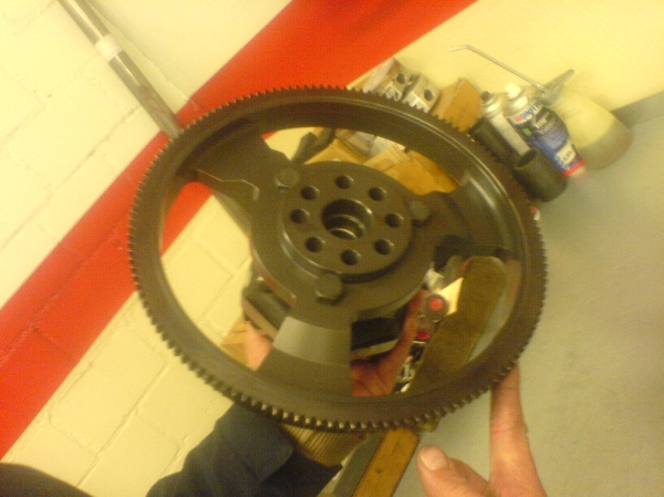
judging by the pics, it looks like the lightening holes are actually behind the mid-weight section of the counterbalance weight. And, they are really only on three quarters of the pulley. The front pulley was also removed.
I assume the front pulley bits weigh more than the scraps from the drilled holes.
So as stated above, you have moved the counterbalance back a bit removing the pulley, and then forward with the lightening holes, and then back with static balancing.
I think you can roughly calculate the rotating mass of the drilled holes and the mass of the removed pulley (and the other bits trimmed off, and their relationship to the original midway point on the crank, and then the change of force acting on a fixed spot, like the center of the first bearing. And then figure how much weight you need to add to the counterbalance to get back to the original measurements.
Save some math, and just use the counterbalance in the up or down position, and then figure a fulcrum to the center of the main bearing, rather than rotating forces.
or I could be way off here...
Re: Crank pulley dynamic balance
Posted: Sun Oct 10, 2010 8:30 pm
by la_strega_nera
scott.venables wrote:
To me it seems that because the counterweight has moved back, and thus the lever is shorter, it needs more counterweight.
Nope, doesn't work that way.
If the lightened pulley balances the same as it used to on your rig, then it's right.
Re: Crank pulley dynamic balance
Posted: Sun Oct 10, 2010 10:55 pm
by scott.venables
Even though I'm only static balancing the jig/pulley assembly?
Re: Crank pulley dynamic balance
Posted: Mon Oct 11, 2010 2:27 am
by Mats
scott.venables wrote:Even though I'm only static balancing the jig/pulley assembly?
Definetly
not!
You always need to balance dynamically. And even that varies depending on speed...
Re: Crank pulley dynamic balance
Posted: Mon Oct 11, 2010 4:29 am
by scott.venables
That's what I thought
Re: Crank pulley dynamic balance
Posted: Mon Oct 11, 2010 7:58 pm
by Jim K
That's why dynamic balance is checked at two speeds one low and one high -don't ask, I don't remember the actual numbers.
Jim K.
Re: Crank pulley dynamic balance
Posted: Wed Oct 13, 2010 7:45 am
by firefox
Re: Crank pulley dynamic balance
Posted: Wed Nov 24, 2010 9:38 am
by Giuliettaevo2
please shoot down the ufo...

Re: Crank pulley dynamic balance
Posted: Wed Nov 24, 2010 10:49 pm
by MD
If that doesn't work try a boomerang behind the left earhole. If all else fails, stick his golf clubs up his arse and use the wood iron to slam the hole shut.